Professional Documents
Culture Documents
Bsi 3939-2 (Iec60617) PDF
Uploaded by
alisolmaz0 ratings0% found this document useful (0 votes)
1K views19 pagesOriginal Title
BSI 3939-2 (IEC60617).pdf
Copyright
© © All Rights Reserved
Available Formats
PDF or read online from Scribd
Share this document
Did you find this document useful?
Is this content inappropriate?
Report this DocumentCopyright:
© All Rights Reserved
Available Formats
Download as PDF or read online from Scribd
0 ratings0% found this document useful (0 votes)
1K views19 pagesBsi 3939-2 (Iec60617) PDF
Uploaded by
alisolmazCopyright:
© All Rights Reserved
Available Formats
Download as PDF or read online from Scribd
You are on page 1of 19
‘BSI BS*3939: PARTH2 65 MM Ub24Bb9 0083629 3
BS 3939 : Part 2: 1985
IEC 617-2: 1983
(© bith Senda Inston. No pao th pation may be patacpld or there reproduced witht the prior permission in wing of BS]
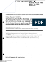
British Standard Guide for
Graphical symbols for electrical power,
telecommunications and electronics diagrams
Part 2. Symbol elements, qualifying symbols and
other symbols having general application
{IEC title: Graphical symbols for diagrams
Part 2: Symbol elements, qualifying symbols and other symbols having general application]
Symboles graphiques pour schémas d’électrotechnique, de télécommunications et
électronique
Partie 2. Eléments de symboles, symboles distinctifs et autres symboles d’ application générale
Schaltzeichen fir Diagramme in der Elektrotechnik. Nachrichtentechnik und Elektronik
® Teil 2, Symbolelemente, Kennzeichen und andere Zeichen fir allgemeine Anwendung
British Standards Institution
Copyright by the British Standards Institution
Sat Oot 11 124d 2008
BST BS¥34/9) PART#2 85 MH 26209 0083630 T
BS 3939: Part 2: 1985
National foreword
This Part of BS 3939, prepared under the direction of the General Electrotechnical Engineering Standards Committee,
recommends symbols, with definitions, for use in electrical power, telecommunications and electronics diagrams; it
comprises graphical symbols for general application, symbol elements and qualifying symbols. Itis identical with the English
textin IEC Publication 617-2 ; 1983 "Graphical symbols for diagrams’, Part 2‘Symbol elements, qualifying symbols and
other symbols having general application* published by the International Electrotechnical Commission (IEC), except that
the English text has been rearranged typographically asa consequence of deleting the corresponding French text.
‘Together with Part 1* and Parts 3to 15, this Part of BS 3939 supersedes the previous edition which is withdrawn in is
entirety
‘Thetitles oF the other Parts in the BS 3939 series areas follows:
Part | General principles*
Part 3 Conductors and connecting devices
Part 4 Passive components,
Part § Semiconductors and electron tubes
Part 6 Production and conversion of electrical energy
Part 7 Switchgear, controlgear and protective devices
Part 8 Measuring instruments, amps and signalling devices
Part 9 Telecommunications: switching and peripheral equipment
Part 10 Telecommunications: uansmuission
Part 11 Architectural and topographical installation plans and diagrams
Part 12 Binary logic elements
Part 13 Analogue elements
Titles to any further Parts will be added in due course.
To take account of the development of computer draughting, the symbols have been designed to arid, A transparent
over-lay with this grid will be included in Part.
‘Terminology and conventions. The text ofthe international standard has been approved for publication as a British Standard
without deviation, Some terminology and certain conventions are not identical with those used in British Standards,
Cross-references
Interational standards Corresponding British Standaris
TEC 445: 1973 [BS 5559 : 1978 Specification for identification of apparatus terminals and general rules fora
uniform system of terminal marking usingan alphanumeric notation
(identical)
180 128-1982, BS 308 : Engineering drawing practice
Part |; 1984 Recommendations for general principles
(Technically equivalent)
BS 3939 Guide for graphical symbols for electrical power, telecommunications and electronics
diagrams
TEC 619-6 1983, Part 6 1985 Production and conversion of electrical energy
(identical)
TEC 617-10; 1983 Part 10: 1985 Telecommunications: transmission
(identical)
TEC 617-12: 1983, Part 12: 1985 Binary logic elements
(Udentical)
TEC 617-13: 1983 Part 13: 1985 Analogue elements
(dentical)
The Technical Committee has reviewed the provisions of IEC 27, IEC 364-3 and IEC 375, to which reference fs made in the
test, and has decided that they are acceptable for use in conjunction with this standard,
‘Compliance with a British Standard does not of Ksetf confer immunity from legal obligations.
* In preparation
Copyright by the Grlsh Standards Tasitaton
Sat Oot 11 12:35:08 2008
ByT_BS*3939: PAKTx2 85 MM 1624bb9 0083631 3
BS 3939: Part 2: 1985
@ Contents
Page
ee ee bevieteeeeseteesee wees Inside front cover
‘Committee responsible. Back cover
List of symbols
Cartan Es Sraumuumsemants voces cece eeees : 2
Section 1 ~ Outlines and enclosures. 2
Coarse I: Quanrmmaseimots . 3
Section 2~ Kind of current and voltage 3
Section 3 Varibitty : ‘4
Section 4 Direction of force or motion s
Section $—Directon off1OW + eee ceeeeveeeeees 6
Section 6 — Operational dependence on a characteristic quantity 6
Section 7 ~Types of material. . 1
Section 8 ~ Effector dependence 1
@ Section 9— Radiation... .. 8
Section 10 ~ Signal waveforms. 8
Section 11 = 9
‘Onn evunore HAVING CENERAL APPLICATION 6.6. e ee eeecs cece . 10
Section 12 -Mecbanical controls... - . 10
‘Section 15 ~ Operating devios and methods. cee cetecttteteesereeees HL
Section 14 - Control by non-clectrial quantities... eee. cite 8
‘Section 15 — Earth ad fame connections, equipotntialty : B
Section 16~ Ideal circuit elements . : seectseeeees 4
Section 17 - Micelaneas my
‘Aprenonx A: Otpmsmmois feo seve 6
Section At ~ Operating device... + cette 6
Copymg by the British Standards Institution
Sat Oot 11 12:35:09 2008
BSI BSx3939: PART#2 65 MM Lb24bb9 0083632 3 mm
BS 3939: Part2: 1985
——_—
British Standard Guide for
Graphical symbols for electrical power,
telecommunications and electronics diagrams
Part 2. Symbol elements, qualifying symbols and other symbols having general application
Seen eee Emel
(CHAPTER I: SYMBOL ELEME!
SECTION | - OUTLINES AND ENCLOSURES
orm | Forms
a
Funetional nit
Note. ~ Suitable symbols or legends shall be inserted in
emo | Fom2 ‘oF added 0 the symbol outline to indicate the
item, equipment oF function
oo10s | Form 3 O
ee-oro | om Envelope (tn)
Enclose
[Noles J. An outline of anothar shape may be weed.
82.01.08 | Form 2 2.=If the enclosure has speci
| wes attention may be dr
“The use ofthe envelope symbol is options
i may be omitted if no confusion will arise
The envelope must be shown if there is @
connection to i, If necessary the envelope
may be split
0201-06 Se Boundary line
[Notes 1. ~ Use to indicate items associated physically,
mechanically or functionally,
‘Any combination of short and long strokes
‘may be wed:
== Sereen (shield)
q ‘Note. The sereen may be drawn in any convenient
hope
| |
EC pages 8 and 9} 2
ida Taatavon
BSI _BS*3939: PARTA2 65 MM Lb24bb5 0083633 5 mm
CHAPTER 1
BS 3939: Part 2: 1985
QUALIFYING SYMBOLS
SECTION 2 - KIND OF CURRENT AND VOLTAGE
mor
wus
2-02.04
omos
02.02.06
2.02.07
o2.02.08
Symbol
Deesrption
2M — 220/10
ot 2
~ 50Hz
\ 100.600 kHz,
3N-\. S0Hz 400/730
3N~\ S0H2/ TN-S.
[Notes 1. ~The voliage may be indicated atthe right of
the symbol andthe type of system atthe lef
Example
Direct éurrent, three conductors including mi.wire,
220 V (110 V between each outer condictor and mid
wire)
2M may be replaced by 24M
2,— Symbol W24I2.05 is to be used i symbol
02-02-01 causes confusion
Alternating eurrent
[Notes 1. ~The numerical value of the frequency oF the
Frequency range may be added at the ight
hand side of the symbel.
Examples
Alternating current of 50 He
Alternating current frequency range 100 KH to 600 kHz
2.—The voltage may also be indicated tthe
Fight ofthe symbol
‘The number of phases and the presence of
neural may be indicated atthe left-hand side
Of the symbol
Example:
Alternating current: three-phase with neutral, 50 Ha,
400 V (230 V between phase and neutral).
SN may be eeplaced by 3++1N
4.~ ICit ip necessary to indicate system in see
cordance with the designation established in
TEC Publication 364-3: Electrical Install
tions of Buildings, Part 3: Assessment of
General Charzctristics, the corresponding
designation should be added to the symbol,
Example:
Alternating current, three-phase, 50 Ha: system having
‘ono poiat directly earthed and reparate nota snd pro
lective conductors throughout
2.02.09
-02.10
wort
eR?
Alternating current, diferent frequency ranges
‘The following symbols may be used when its necessary
fom a given craving 10 distinguish between the citlerent
Frequency ranges
Relatively low frequencioe(onamplo: power fequencis
‘or sub-audio frequencies)
Medium frequencies (example: audio)
Relatively high frequencies (example: super audio
carrer and radio frequencies)
wna
Copymgt by the British Standards Institution
Sat Oot 11 12:35:09 2008
Rectified current with alternating component (it iti
necessary to distinguish from a stedy-cirect current)
EC pages 10 and 11]
BSI BSx3939: PARTS? 85 MM LL2ULL9 OO83L34 7 Ml
BS 3939: Part 2: 1986
No - Descnon e
wma + Positive polarity
nia - Negative polarity
wins N Neutral
‘Note. ~ This symbol fr neutral given in TEC Publica
i sion 445: Mentifcation of Apparatus Terminals
v4 General Rules for a Uniform System of
Terminal Marking, Using an Alphanumeric
| cation 445,
SECTION 3—VARIABILITY
3.1 Variability is non-inherent when the variable quantity 1s controtted by an external device, for example, when
the resistance is controlled by a regulator.
4.2. Variability is inherent when the variable quantity depends on qualities of the device itself, for example, when
the resistance changes with change of voltage or with chango of temperature,
3.3 Thesign for variability should be drawn across the main symbol at about 45 * to the centre line ofthe symbol.
No, Symbol
Pasion
enum Variability, non inherent
e034
mane Variability, inherent
‘ate, Information on the controlling quantity, for
example vollage or temperature, may be shown
near the symbol
Variability. inherent, non-linear
The
ote with symbol (2-03.03 apples.
te
asas Prost adjustment
nN
Information on the conditions under which
sdjustment is permitted may be shown near
the symbol
Prost adjustment penmitted only at zero current
/
/
/
>
D
EC pages 11, 12 and 13] 4
Copyrgh by The Tesh Sandards Tasitaton
Sat Oot 11 12:35:09 2008
‘bb24bb5 0063635 9 Ml
BS 3939: Part 2: 1985
BSI_BS*3939: PART*2 85 Ml
r-
e 5 9 |
aoa o arti ses
Serio
Note i eight tte ye
ue
eee 5 —
Le | Yor non tkra n e sepe
eos y Comins vai
woo y snp
va Pre-set adjustment, continuously variable
e aon Avent mea
J Nash snl quctly may be indented
ric tsa
8
woe —
4
Db Amplifier with automate gain control
SECTION 4—DIRECTION OF FORCE OR MOTION
‘An arrow may be used to indicate the direction in which the movable part of a symbol must move ta give a
required effect (see the example of symbol 02-04-02).
4d
It may also indicate the direction of a fores or the direction of motion of the physical part symbolized. In
such cases a note to indicate the view point may be required,
4.2. The effect caused by movement may be explained by symbols orby a text.
Frequency
decease SE rset
ah
chet
02-04-06 Ny Reciprocating motion -
Copymg by the British Standards Institution
Sat Oot 11 12:35:09 2008
EC pages 13 and 14)
“BST BS*3999: PART#2 85 MM Db2466 OOS3b3b O
BS 3939: Part2: 1985
SECTION 5
.CTION OF FLOW
EC pages 15 and 16]
Copyright by We Tesh Sandards Tasituton
Sat Oot 11 12:35:09 2008
No. Symbol Description
(20st —_—>— Propagation, energy flow, signal Now, one way
2asin ee Propagation, both ways simaltaneouly
e2osin <3 | Propagation, both ways, not simultaneously
‘Alternate tanemision and reception
(2.0504 — Transmission
Wore, ~The dot may be omiited if tho sense is unam-
‘uous given by the sromhend in combina
tion with the sy to whic ts api. Por
j example see symbol 10-06-04,
asa => Reception
Note. ~"The dot may be omitted ifthe sense nom
| Biguouy ven bythe acowhead i combina
thn wth te symbol to whic tapped For
‘tamptesee symbol 10-0603.
eos bo Energy flow fom the busbar
cease | a Energy flow towards the bushars
coasox he Bisretonal energy ow
SECTION 6 - OPERATIONAL DEPENDENCE ON A
CHARACTERISTIC QUANTITY
No Symbol Description
ra Operating when the chareteristie quantity i higher
> than the setting value
wanin < Operating when the characeniste quantity iower than
the setting value
cen Operating whon the characteristic quantity i €
2 Dover han elven hgh sting or wer than wien
low sting
(eae 0 Operating wien value OF the charscterste quantity
cea wo Operating when the vale of the characteristic quay
{irs ron zero by a amount whi very sal come
pated wth the normal vale
BSI_BS*3939: PARTH2 85 MM 2624669 0083637 2 mm
BS 3939: Part 2: 1985
@ SECTION 7—TYPESOF MATERIAL
7.1 Tho type of material may be indicated either by using ite ohomical eymbol, or by one of the qualifying symbols
siven below. These symbols have been drawn in rectangles, but the rectangle may be omitted when they are
used in conjunction with another symbol. Ifnecessary, use may be made of the symbols for materials given in
180 128 : Engineering drawing — Principles for presentation.
No. Symbol Description
coro Material, unspecified
e 2-07-04 Material, gas 7
2-07.05 Material, clectret |
coors Mai semondig
SECTION 8 - EFFECT OR DEPENDENCE
ms eta =
eae 4 Thema ce
woe = vegcncie woe —|
e woos x Mapai cit or pies
tones — bony
7 EC pages 17 and 18]
Copymg by the British Standards Institution
Sat Oot 11 1235-10 2008
BS 3939: Part 21985
BSI BSx3939: PART#2 65 MM Lb24bb5 0083638 4 Me
SECTION 9—RADIATION
9.1 Arrows pointing towards a symbol denote that the device symbolized will respond to incident radiation of the
‘indicated type.
9.2 Arrows pointing away from a symbol denote the emission f the indicated type of radiation by the device
symbolized.
9.3 Arrows located within a symbol denote a self-contained radiation source.
No. Symbol Description
2.09.01 Radiation, nonioizing. electromagnetic (Cor ©
y radio waves oe ae ght)
2.90 &
mas
Radiation,
izing
Noe. IC iis necessary to show the specific type of
jonizing radiation, the symbol may be. aug:
mented by the addition of symbols or letters
such asthe following:
se alpha partite
beta particle
Y= gamma rays
deuteron
proton
x= pion
x= K meson
SECTION 10- SIGNAL WAVEFORMS
104 seh symbotrepreents need shape ofthe waveform.
[wo ~ Symbot T eset ~
2.10400 mw Sawtooth ~
EC pages 19 and 20}
Copyright by the Ritch Standards Institution
Sat Oot 11 1235-10 2008
BSI_BS*3939"
‘SECTION
PART¥2 85 MM b24bb9 0083639 b a
BS 3939 : Part 2: 1985
11 PRINTING, PERFORATING AND FACSIMILE
Copyright by the British Standards Institution
Sat Oot 11 1235-10 2008
No. ‘Symbo! Deserption
e@.ttot —_ “Tape printing
ca = Tape perforating or using perforated tape
Carry Simultapcous printing and perforating of one tape
aos ca Page printing
@aros oe Keyboard
mts os
9 IEC page 21)
BST BS¥3939: PART#2 85 MM Lb24bb9 0083640 2 mm
BS 3939: Part 2: 1985
(CHAPTER II: OTHER SYMBOLS HAVING @
GENERAL APPLICATION
SECTION 12 - MECHANICAL CONTROLS
‘Mechanical connection (link)
Pouratie connection (link)
Hydraulic connection (link)
waza — Examples:
Mechanical connection with indication of direction of
Force oF motion
Foren t
i208 > Mechanical connection with indication of direction of
[Notes 1, ~The arrow i assumed tobe placed infront of
the connection symbol.
| ; Sus = r
& Nate = Dele ston nthe dst of movement
‘Note, ~"The triangle is pointed in the return direction.
Detent
[Nom-automatic return
Device for maintaining a given postion
0212.0) 1 Dotent, disengaged
Deen caged ®
Latching device, disengaged
Latchine devs, engaged
‘Bock deviee
EH
wns ‘locking. device engaged, movement (9 the left Is
blocked
~ ‘Giueh
Mechanical coupling
Mechanical
pling, disengaged
(HEC pages 22 and 23} 10
Dopyrghe by the Mesh Sandards Tastaton
Sat Oot 11 1235-10 2008
BS*3939! PART#2 65 MM 3b24bb9 008364) 4 Ml
BS 3939: Part 2: 1986
@ % Sot =
ont2.18 th Mechanical coupling, enpaged
ae tty. Eval:
Unidiretional coupling device for rotation
Pre wel
conan a wae
conn —
@-=- etre motor wih brake applied
ona a eee mor wih bts eee
‘Gearing
No. Symbol Description
om-13.01 f---- Manually operated contro, general ease
ane Manually operated contro with
13.03 + Operated by ps
213.08 Operated by turning
23-05 Operated by panting
213-06 0 Operated by proximity effect
2.13.07 Operate by touching
7-13.08, Emergency switch (mushroom-head safety feature)
02.13.09 @ Operated by handheel
13.10 ya ‘Operated by pedal
" {HEC pages 23 and 24)
Copyright by the British Standards Institution
Sat Oot 11 1235-10 2008
BS 3939: Part 2: 1985
“BSI BS*3939: PARTH2 85 MM Db2ULL4 OOS3LN2 b A
Deseription
Operated by lever
Operated by emovable handle
conn
Pease
|
| eas
Operated by hoy
‘Operated by crank
[EC pages 25 and 26)
Copyrghe by Whe Tesh Standards Tastaton
Sat Oot 11 1235-10 2008
12
| oeasas Operated by roller
144
BSI BS*3939: PARTA2 65 MM Ub24669 0083643 6 mm
SECTION 14~CONTROLLED BY NO!
BS 3939: Part 2: 1985
)N-ELECTRICAL QUANTITIES
Letter symbols from IEC Publication 27 : Letter Symbols to be Used in Flectrical Technology, may be used
to denote other operating quantities than those shown below (for example pressure or speed). They should be
enclosed in a rectangle ifambiguity could otherwise arise.
No,
‘Symbol
Description
401
Control by tui feel
on
ots
07-14-04
Control by number of events
Control by a counter
Control by flow
Bxample:
Control by gas flow
or-140s
[7oH,0}
Control by relative humidity
SECTION 15—EARTH AND FRAME CON!
NECTIONS, EQUIPOTENTIALITY
no symbot Deseiption
Cound gnc snot
Not. = Supplementary aration ay giant de
fine the satis or the purpose ofthe earth itis
isnot readily apare
nasa Notes earth
e Noises prod
mises Protstive cath
Protetve ground
Note. =o pl ay be sed in place of sybot
{D-1Stoindeate an cath conection faving
* spel protective fncton for example or
froveton feat slenea shosk insite of
fa
caisot Fane
Chasis
m :
Note. ~The htcing maybe completly or promi
ted if there fs no ambiguity If the hatching
tite the ne reeset, the
Chas tal tik shown baw
@ casos Euipotentiy
Copymg by the British Standards Institution
Sat Oot 11 1235-10 2008
13
UBC pages 27 and 28]
BSI BS*3939: PART#2 85 MM Lb24bb9 OO83L44 T Ml
BS 3939: Part 2: 1985
SECTION 16—IDEAL CIRCUIT ELEMENTS
16.1 Additional indieations may be added to the symbols 02-16-01 to 02-16-03 according to IEC Publication 375
‘Conventions Concerning Electric and Magnetic Circuits.
Ww. Symbot Desspion
601 } ca curent sure
zone Tel vlage ure
aon Weal gyrtor
SECTION 17 - MISCELLANEOUS
‘ Symbol Decision
worran rule
4 (ication of assed fal eatin)
wine Fadover
L Breakthrough
cones 7 Permanent magnet
wana — Moving (for example ing) contact
' Exumples of use
-
{UEC pages29 and 30) 14
Copyrghe by The Tesh Standards Tastuton
Sat Oot 11 1235-10 2008
PART#2 65 WM Lb24bb9 OO83b45 1 a
BS 3939: Part
BSI_BS*393)
985
- |
a.7.06 Changer, general symbo!
Converter, general symbol
“| Notes 1, —1f the direction of change isnot obvious, it
may be indicated by an strowhead on the
‘urtne ofthe sym
A symbol or legend indicating the fs
‘output quantity, waveform ete. may be ine
serted in each half ofthe general symbol to
‘how the satura of the change
See IEC Publication 617-6: Production and
‘Conversion of Electrical Energy,
Publeation “617-10: “Telecom
‘Transmission,
43.» The diagonal line ftom tis symbol is used in
the form of a solidus to show a converting
function.
See IEC Publication 617-12: Binary Logie
e Elements, and TEC Publication 617-13
Analogue Blements
waar Galvanic separator
xy ‘Note. ~ i necessary, indication ofthe way of separation
may be given below the qualifying symbol,
forexample: X//Y
7.08 n Identities of analogue signals
‘Note. ~The symbol shall be wed only when it is neces-
sary (0 distinguish between unalogue ane digital
signals,
wor7-09 # ‘Menuier of aga signals
‘The note with symbot 02-17-08 apples
ote. — A time-
You might also like
- The Yellow House: A Memoir (2019 National Book Award Winner)From EverandThe Yellow House: A Memoir (2019 National Book Award Winner)Rating: 4 out of 5 stars4/5 (98)
- Bsi 3939-4 (Iec60617) PDFDocument12 pagesBsi 3939-4 (Iec60617) PDFalisolmazNo ratings yet
- Hidden Figures: The American Dream and the Untold Story of the Black Women Mathematicians Who Helped Win the Space RaceFrom EverandHidden Figures: The American Dream and the Untold Story of the Black Women Mathematicians Who Helped Win the Space RaceRating: 4 out of 5 stars4/5 (895)
- Bsi 3939-13 (Iec60617) PDFDocument16 pagesBsi 3939-13 (Iec60617) PDFalisolmazNo ratings yet
- The Subtle Art of Not Giving a F*ck: A Counterintuitive Approach to Living a Good LifeFrom EverandThe Subtle Art of Not Giving a F*ck: A Counterintuitive Approach to Living a Good LifeRating: 4 out of 5 stars4/5 (5794)
- Bsi 3939-6 (Iec60617) PDFDocument20 pagesBsi 3939-6 (Iec60617) PDFalisolmazNo ratings yet
- The Little Book of Hygge: Danish Secrets to Happy LivingFrom EverandThe Little Book of Hygge: Danish Secrets to Happy LivingRating: 3.5 out of 5 stars3.5/5 (399)
- Bsi 3939-11 (Iec60617) PDFDocument16 pagesBsi 3939-11 (Iec60617) PDFalisolmazNo ratings yet
- Devil in the Grove: Thurgood Marshall, the Groveland Boys, and the Dawn of a New AmericaFrom EverandDevil in the Grove: Thurgood Marshall, the Groveland Boys, and the Dawn of a New AmericaRating: 4.5 out of 5 stars4.5/5 (266)
- Bsi 3939-8 (Iec60617) PDFDocument15 pagesBsi 3939-8 (Iec60617) PDFalisolmazNo ratings yet
- Shoe Dog: A Memoir by the Creator of NikeFrom EverandShoe Dog: A Memoir by the Creator of NikeRating: 4.5 out of 5 stars4.5/5 (537)
- Bsi 3939-3 (Iec60617) PDFDocument11 pagesBsi 3939-3 (Iec60617) PDFalisolmazNo ratings yet
- Elon Musk: Tesla, SpaceX, and the Quest for a Fantastic FutureFrom EverandElon Musk: Tesla, SpaceX, and the Quest for a Fantastic FutureRating: 4.5 out of 5 stars4.5/5 (474)
- Bsi 3939-9 (Iec60617) PDFDocument18 pagesBsi 3939-9 (Iec60617) PDFalisolmazNo ratings yet
- Never Split the Difference: Negotiating As If Your Life Depended On ItFrom EverandNever Split the Difference: Negotiating As If Your Life Depended On ItRating: 4.5 out of 5 stars4.5/5 (838)
- Bsi 3939-5 (Iec60617) PDFDocument28 pagesBsi 3939-5 (Iec60617) PDFalisolmazNo ratings yet
- Grit: The Power of Passion and PerseveranceFrom EverandGrit: The Power of Passion and PerseveranceRating: 4 out of 5 stars4/5 (588)
- Bsi 3939-6 (Iec60617) PDFDocument20 pagesBsi 3939-6 (Iec60617) PDFalisolmazNo ratings yet
- A Heartbreaking Work Of Staggering Genius: A Memoir Based on a True StoryFrom EverandA Heartbreaking Work Of Staggering Genius: A Memoir Based on a True StoryRating: 3.5 out of 5 stars3.5/5 (231)
- Bsi 3939-5 (Iec60617) PDFDocument28 pagesBsi 3939-5 (Iec60617) PDFalisolmazNo ratings yet
- Bsi 3939-11 (Iec60617) PDFDocument16 pagesBsi 3939-11 (Iec60617) PDFalisolmazNo ratings yet
- The Emperor of All Maladies: A Biography of CancerFrom EverandThe Emperor of All Maladies: A Biography of CancerRating: 4.5 out of 5 stars4.5/5 (271)
- Bsi 3939-2 (Iec60617) PDFDocument19 pagesBsi 3939-2 (Iec60617) PDFalisolmazNo ratings yet
- Bsi 3939-9 (Iec60617) PDFDocument18 pagesBsi 3939-9 (Iec60617) PDFalisolmazNo ratings yet
- The World Is Flat 3.0: A Brief History of the Twenty-first CenturyFrom EverandThe World Is Flat 3.0: A Brief History of the Twenty-first CenturyRating: 3.5 out of 5 stars3.5/5 (2259)
- Bsi 3939-11 (Iec60617) PDFDocument16 pagesBsi 3939-11 (Iec60617) PDFalisolmazNo ratings yet
- On Fire: The (Burning) Case for a Green New DealFrom EverandOn Fire: The (Burning) Case for a Green New DealRating: 4 out of 5 stars4/5 (73)
- Medium Voltage SwitchgearDocument2 pagesMedium Voltage SwitchgearalisolmazNo ratings yet
- The Hard Thing About Hard Things: Building a Business When There Are No Easy AnswersFrom EverandThe Hard Thing About Hard Things: Building a Business When There Are No Easy AnswersRating: 4.5 out of 5 stars4.5/5 (344)
- Bsi 3939-8 (Iec60617) PDFDocument15 pagesBsi 3939-8 (Iec60617) PDFalisolmazNo ratings yet
- Bsi 3939-4 (Iec60617) PDFDocument12 pagesBsi 3939-4 (Iec60617) PDFalisolmazNo ratings yet
- Team of Rivals: The Political Genius of Abraham LincolnFrom EverandTeam of Rivals: The Political Genius of Abraham LincolnRating: 4.5 out of 5 stars4.5/5 (234)
- Bsi 3939-6 (Iec60617) PDFDocument20 pagesBsi 3939-6 (Iec60617) PDFalisolmazNo ratings yet
- Monitoring Ageing CCVTsDocument12 pagesMonitoring Ageing CCVTsRenato FelicioNo ratings yet
- Bsi 3939-9 (Iec60617) PDFDocument18 pagesBsi 3939-9 (Iec60617) PDFalisolmazNo ratings yet
- The Unwinding: An Inner History of the New AmericaFrom EverandThe Unwinding: An Inner History of the New AmericaRating: 4 out of 5 stars4/5 (45)
- Bsi 3939-5 (Iec60617) PDFDocument28 pagesBsi 3939-5 (Iec60617) PDFalisolmazNo ratings yet
- The Gifts of Imperfection: Let Go of Who You Think You're Supposed to Be and Embrace Who You AreFrom EverandThe Gifts of Imperfection: Let Go of Who You Think You're Supposed to Be and Embrace Who You AreRating: 4 out of 5 stars4/5 (1090)
- Sizing and Selection of Grounding TransformersDecision CriteriaDocument5 pagesSizing and Selection of Grounding TransformersDecision CriteriaKhashane Willy Mohale100% (1)
- Referenzen Ab 2003...Document6 pagesReferenzen Ab 2003...alisolmazNo ratings yet
- GIS RC Voltage DividerDocument6 pagesGIS RC Voltage DividerEldin EnggNo ratings yet
- On-Site Testing of GIS With Ac VoltageDocument6 pagesOn-Site Testing of GIS With Ac VoltagesabahabeebNo ratings yet
- Mitigating Ferroresonance in HV Inductive Transformers: Abstract - FerroresonantDocument5 pagesMitigating Ferroresonance in HV Inductive Transformers: Abstract - FerroresonantalisolmazNo ratings yet
- Technical Engineering Notes: UPS SystemsDocument3 pagesTechnical Engineering Notes: UPS SystemsalisolmazNo ratings yet
- The Sympathizer: A Novel (Pulitzer Prize for Fiction)From EverandThe Sympathizer: A Novel (Pulitzer Prize for Fiction)Rating: 4.5 out of 5 stars4.5/5 (121)
- CCVT PDFDocument16 pagesCCVT PDFCézar NobreNo ratings yet
- 09 F TRN 0154Document7 pages09 F TRN 0154kuzi_13No ratings yet
- Her Body and Other Parties: StoriesFrom EverandHer Body and Other Parties: StoriesRating: 4 out of 5 stars4/5 (821)

